


When two dissimilar metals are joined at two junctions, they generate what is known as an electromotive force (emf). This emf arises due to varying temperatures of the two junctions of the circuit, and it may even exist due to a temperature gradient along the entire length of the conductors within the circuit. The three principles detailed here are the Seebeck effect, the Peltier effect, and the Thomson effect (although this one is far less common), and they form the basis for thermocouples.
Thermocouples, quite simply, are devices that measure temperature. Standards have long been crucial for the use and management of thermocouples in both science and industry. Most users of thermocouples may be familiar with ANSI MC96.1, which gave tables detailing calibration types, thermocouple tolerances, and some other information. Today, temperature-electromotive force (emf) relationships for common thermocouple types are found in reference tables of NIST’s ITS 90 Thermocouple database. Similar information, as well as further guidance, is in ASTM E230/E230M-23a: Standard Specification for Temperature-Electromotive Force (emf) Tables for Standardized Thermocouples.
Since thermocouples make use of the relationship between heat, electricity, and multiple metals, they are susceptible to some issues, for which further standards offer specifications and guidance. However, before we discuss these, it is worthwhile to explain thermocouples themselves.
What Are Thermocouples?
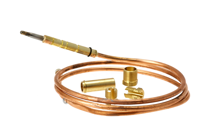
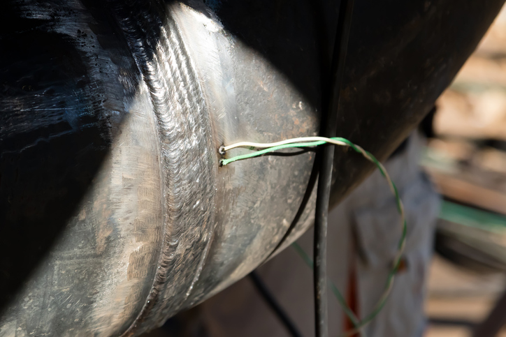
Thermocouples consist of two wires of different metals welded together at each end. Each type is classified by its alloy combination. For example, Type J thermocouples contain one iron wire and one constantan copper-nickel wire (these types are sometimes known as an “ANSI Code” or “ANSI Type,” since they were once classified in ANSI MC96.1).
Since electrons in metals carry both heat and electricity, thermocouple voltage is a side effect of heat flow. Each material used as wires (thermoelements) of a thermocouple has a different emf response to a temperature gradient. Due to the Seebeck effect, where a temperature difference exists, there is also a charge imbalance. From this phenomenon, a voltage is generated, and the difference between the two emfs in each wire results in the measured emf of the thermocouple.
Therefore, please note that the Seebeck effect occurs in the bulk of the metal, and, in a well designed thermocouple installation, the junction contributes nothing to the voltage.
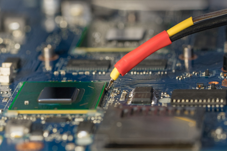
While they are used in science, thermocouples have found usage across a vast range of industries, from energy generation to pulp and paper. They are also found in some ovens and other kitchen appliances.
ANSI MC96.1 – Calibrating Thermocouple Temperature and Legacy
Some thermocouple devices actually display temperature directly, but the conversion is generally done through the following equation provided by NIST:
T = d0 + d1v + d2v2 + d3v3 + d4v4 + . . . d9v9
Where “the di are calibration coefficients taken from the NIST database, T is the thermocouple temperature (in °C), and V is the thermocouple voltage (in millivolts). The thermocouple voltage is either referred to a cold junction at 0°C, or it is a compensated voltage as though it were referred to a cold junction at 0°C.”
However, since a single equation doesn’t work well over the wide temperature range of a thermocouple, NIST breaks up the range into smaller portions and publishes calibration coefficients for each.
Many thermocouple users simply make use of reference tables. Throughout the ‘70s and ‘80s, these tables were found in ANSI MC96.1. However, in 1989, NIST adopted these reference tables in NIST ITS-90, and you can view them at the NIST ITS-90 Thermocouple Database.
Types of Thermocouples
The thermocouple type derives from the components of the two metal wires used. The choice of thermocouple depends on several factors, and each type detects a specific temperature range. Overall thermocouple choice is based primarily on temperature range, reaction time, abrasion / vibration resistance, chemical resistance, calibrations, installation, and compatibility.
According to ASTM E230/E230M-23a, thermocouple types include:
Type B – Platinum-30 % rhodium (+) versus platinum6-% rhodium (−)
Type E – Nickel-10 % chromium (+) versus copper-45% nickel (constantan) (−)
Type J – Iron (+) versus copper-45 % nickel (constantan) (−)
Type K – Nickel-10 % chromium (+) versus nickel-5 % (aluminum, silicon) (−)
Type N – Nickel-14 % chromium, 1.5 % silicon (+) versus nickel-4.5 % silicon-0.1 % magnesium (−)
Type R – Platinum-13 % rhodium (+) versus platinum (−)
Type S – Platinum-10 % rhodium (+) versus platinum (−)
Type T – Copper (+) versus copper-45 % nickel (constantan) (−)
Type C – Tungsten-5 % Rhenium (+) versus Tungsten26 % Rhenium (−)
Other Thermocouple Standards
You can get ASTM E230/E230M-23a from the ANSI Webstore, and in it, you can find a range of information on thermocouple tolerances, color-coding, temperature limits, and similar topics. However, this is by no means the only voluntary consensus document poised to provide guidance on the reliable usage and design of thermocouples. Since ANSI deals with standards, we have a responsibility to inform you of these documents. Some other thermocouple standards developed by ANSI-accredited standards developing organizations include:
ASTM E220-19: Standard Test Method for Calibration of Thermocouples By Comparison Techniques
ASTM E2846-20: Standard Guide for Thermocouple Verification
ASTM E839-23: Standard Test Methods for Sheathed Thermocouples and Sheathed Thermocouple Cable
IEC 60584-1 Ed. 3.0 b:2013 – Thermocouples Part 1 EMF specifications and tolerances
The above standards deal with general concepts associated with thermocouples and EMFs, but it is important to remain aware that the needs of thermocouples can vary between industries. Some standards specific to the use of these devices within a certain industry include:
Thermocouples are valued as temperature-taking devices across the spectrum of industry for numerous reasons; they can measure among a wide temperature range, are highly durable, and can be grounded, just to name a few of these benefits. It is only fitting that these devices are kept reliable and efficient. You can find more thermocouple standards by searching the ANSI Webstore.