ISO 21940-21:2022 – Mechanical Vibration, Rotor Balancing
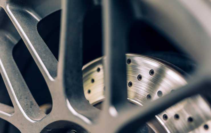
Rotor balancing helps maintain an uninterrupted driving experience, ensuring no vibrations and that wheels are rotating smoothly. The requirements for evaluating rotor balancing in machines for safe and efficient operation in machinery are detailed in ISO 21940-21:2022—Mechanical Vibration, Rotor Balancing.
What Is a Rotor?
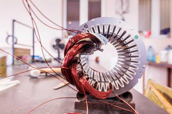
A rotor is a moving, rotating component of an electromagnetic system. It requires existing motion to function, and its rotation is caused from the interaction between the winding and magnetic fields that produces a torque around the rotor’s axis. An amusement ride, The Human Spinning Rotor or “The Rotor,” operated in the mid-20th century at carnivals, teaching riders how rotors physically worked by spinning them in a giant upright barrel. The rotation of the barrel created a centrifugal effect. Once the barrel reached full speed, the floor retracted, which resulted in riders becoming stuck to the wall of the drum, and, at the end of the ride cycle, the drum slows, enabling gravity to take over.
Why Is Rotor Balancing Important?
Rotor balancing is the process of equalizing the distribution of mass across the rotational axis to ensure that there are no imbalances. Unbalance in a rotor is thus the result of an uneven distribution of mass, causing the rotor to vibrate and produce excessive noise. The centrifugal force exerted by the load from an unbalanced rotor will cause wear to the rotor, the bearings and mountings holding it in place, and the machine’s structural support. High levels of vibration from unbalance can further cause equipment to operate less reliably, resulting in increased energy usage, decreased operational efficiency, and reduced equipment service life. Balancing of rotors is therefore important because it prevents excessive loading of bearings and avoids fatigue failure, thereby increasing the useful life and structural integrity of machinery.

What is ISO 21940-21:2022?
ISO 21940-21:2022 provides requirements for evaluating hard and soft bearing balancing machines that support and rotate:
- Rotors with rigid behavior at balancing speed (as described in ISO 21940-11:2016)
- Rotors with shaft elastic behavior and balanced in accordance with low speed balancing procedures (as described in ISO 21940-12:2016).
Rotors are grouped into two categories: rigid and flexible. Rigid rotors, as detailed in ISO 21940-11, can be balanced at lower speeds, as long as there is sufficient centrifugal force to detect the unbalance; flexible rotors, as specified in ISO 21940-12, deflect outward from the rotational axis, and the center of rotation moves away from the rotational axis as the speed increases.
ISO 21940-21:2022 also describes tests to be performed during the acceptance testing of a balancing machine to ensure that the balancing machine is capable of handling the actual balancing tasks. The standard emphasizes that a rotor specific calibration should be performed to establish the machine accuracy at a specific speed and for a rotor of a particular mass.
The Rotors Types in ISO 21940-21:2022
The standard species the methods and requirements for preparing proving rotors that can be of Type A, Type B, Type C, or a User Defined Rotor, allowing a wide range of applications to be covered.
- Type A: Rotors without journals, balanced on a vertical machine (or balanced on a horizontal machine with integrated spindle), in one or two correction planes. Service bearing planes may be anywhere (e.g., one on each side, or both on one side of the main rotor body). For the tests described in ISO 21940-21:2022, it is assumed that one bearing is on each side of the rotor.
- Type B: Inboard rotors with journals, balanced on a horizontal machine, mostly with two correction planes between the bearings. Service bearings are positioned on either side of the rotor.
- Type C: Outboard rotors with journals, balanced on a horizontal machine, with two overhung correction planes. Service bearing positions are similar to those on the proving rotor.
- User Defined Rotors: Rotors used to meet the requirements of a specific application or where a Type A, Type B or Type C rotor is not suitable. The user defined proving rotor replicates the mass, geometry, and inertia of the rotor to be balanced and can be manufactured to replicate a typical rotor to be balanced or be a modified production rotor.
Changes Made to ISO 21940-21:2022
ISO 21940-21:2022 is the 21st part of the ISO 21940 series for balancing technology and includes technical revision. This second edition replaces its predecessor, ISO 21940-21:2012. The main changes in ISO 21940-21:2022 are as follows:
- The introduction of new computer based technology into balance machine indication systems.
- The introduction of additional tests for repeatability and speed range (see Annex F and Annex G).
- The introduction of greater clarification for use with automated and special purpose machines.
Technical Committee ISO/TC 108, Mechanical vibration, shock and condition monitoring, Subcommittee SC 2, Measurement and evaluation of mechanical vibration and shock as applied to machines, vehicles and structures, prepared this standard.
ISO 21940-21:2022—Mechanical Vibration, Rotor Balancing is available on the ANSI Webstore.