ANSI/ISA 5.1-2024: Instrumentation Symbols & Identification

Instrumentation symbols serve as a universal visual language in industrial engineering, representing measurement devices, control instruments, and automation components within process diagrams to assure systems are accurately designed, interpreted, and maintained. ANSI/ISA 5.1-2024: Instrumentation Symbols and Identification establishes the graphical symbols and tagging conventions used in Piping and Instrumentation Diagrams (P&IDs), to depict sensors, controllers, valves, and other automation components.
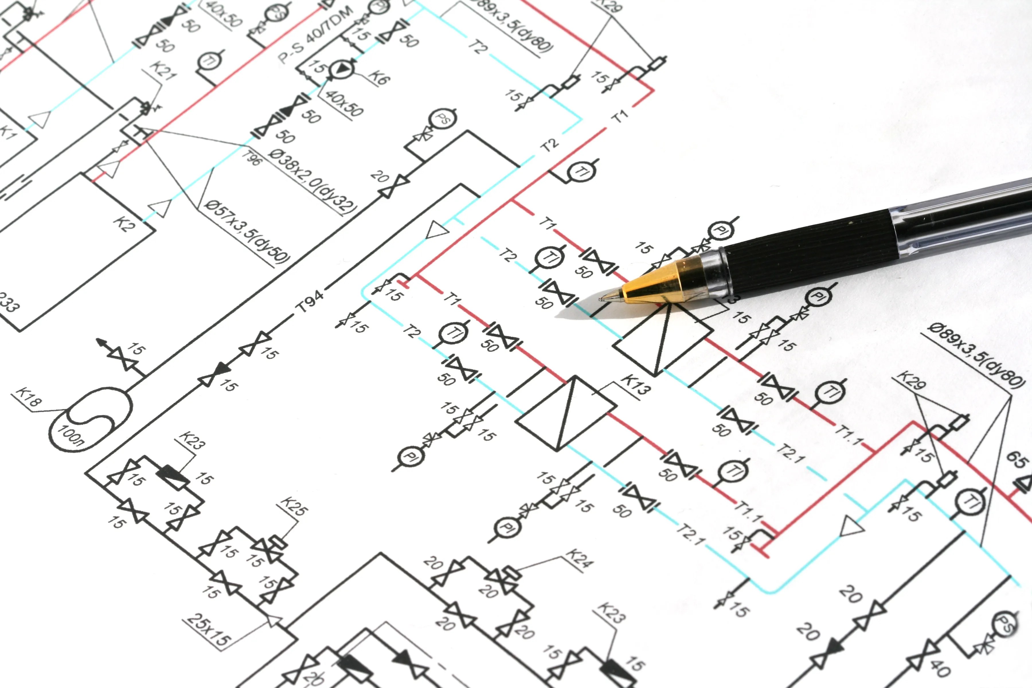
What Is a Piping and Instrumentation Diagram (P&ID)?
A piping and instrumentation diagram (P&ID) is a detailed, industry-standard schematic drawing that illustrates the functional, interconnected relationships between process equipment, piping, and control instruments within a plant. P&IDs map out functional relationships between equipment, piping, and instrumentation for chemical, pharmaceutical, power, and manufacturing facilities.
These diagrams use standardized symbols, primarily based on the ANSI/ISA 5.1-2024 to graphically represent instruments, sensors, controllers, and valves, defining their functional relationship, location, and interconnection within a process system.
What Is ANSI/ISA 5.1-2024?
ANSI/ISA 5.1-2024 establishes uniform means of depicting and identifying instruments or devices. The standard specifies the inherent functions, systems, and applications of instruments used for measurement, monitoring, and control. The symbols and identification methods set forth in ANSI/ISA 5.1-2024 are intended to serve as conceptualizing aids, design tools, teaching devices, and concise and specific means of communication in all types of technical, engineering, procurement, construction, and maintenance documents. This largely includes piping and instrumentation diagrams (P&IDs).
The goal of this American National Standard is to meet the procedures of various users who need to identify and graphically depict measurement and control equipment and systems.
Common Instrumentation Symbols Used in P&ID Diagrams
To read and understand engineering fluid diagrams and prints, usually referred to as piping and instrumentation diagrams (P&IDs), a user must be familiar with basic symbols. Here are some examples of instrumentation symbols and their use:
Centrifugal Pumps
Centrifugal pump is used to transport fluids to the hydrodynamic energy of the fluid flow. It converts the input power to kinetic energy in the liquid by accelerating the liquid by an impeller.
Vacuum Pump
Vacuum pump is a device that removes gas molecules from a sealed volume in order to leave behind a partial vacuum.
Gear Pump
A gear pump uses the meshing of gears to pump fluid by displacement.
Controller
Controller has an output that varies to regulate a controlled variable in a specific way.
Control Valve
The control valve directly manipulates the flow of one or more fluid process streams.
Pressure Indicator Control
The pressure indicator control regulates positive or negative vacuum pressure.
Flow Control Valve
A flow control valve regulates the speed of motors or cylinders within in a system.
Converter
A coverter receives information as one form of an instrument signal and transmits an output signal as another form, such as a current-to-pneumatic signal converter.
Condenser
A condenser is a device for reducing a gas or vapor to a liquid.
Furnace
The furnace is a device used for heating.
Boiler
A boiler is a closed vessel in which water or other fluid is heated. The fluid does not necessarily boil.
Motor
The motor is a device that creates motion. It usually refers to an engine of some kind.
Reducer
The reducer is the component in a pipeline that reduces the pipe size from a larger to a smaller bore (inner diameter).
Separator
Separator refers to a mechanical device to separate fluids and solids.
How P&ID Tag Numbers Identify Instrument Functions
P&ID tag symbols are alphanumeric codes inside bubbles (circles, squares, or diamonds) that identify instrument functions, locations, and loop numbers based on ANSI/ISA 5.1-2024 standards. A tag number with a circle around it, for instance, indicates stand alone, physical instruments.
When a first letter is used in instrumentation symbols, e.g., Pressure Indicator Controller (PIC), it defines the measured or initiating variables. Examples include Analysis (A), Flow (F), Temperature (T), and Pressure (P). The second letter tells the type of device being used, such as Indicator (I), Record (R), and Transmit (T). The third, fourth, or fifth letter tells the function of the component.
What’s New in ANSI/ISA‑5.1‑2024?
Below is a summary of changes made to ANSI/ISA-5.1:2022 to arrive at the ANSI/ISA 5.1-2024 revision:
Title
The title was updated from “Instrumentation Symbols and Identification” to “Instrumentation and Control Symbols and Identification”—emphasizing the inclusion of control-related symbol.
Organization
Rather than having all notes preceding all tables, ANSI/ISA 5.1 was reorganized to place the notes for a table or group of tables immediately following the respective table(s) title. The numbering of tables from subclause-based were changed to simple sequential, and the “Definitions”(Section 3) of the 2022 and 2024 version was re-formatted.
Terms, Definitions, and Abbreviations (i.e., Section 3)
Terms and abbreviations that were not used in the body of the standard were removed, and a few definitions were changed to match and/or reference other standards. Synonyms were placed together rather than appearing separately and referring to each other.
Symbol Changes:
- Table 3 (previously 5.1.2), “Instrumentation device or function symbols, miscellaneous”: Added symbols 6 b), 8, 9, 10, and 11, which includes symbols for shared display, shared control alarm, and remote setpoint (SP) to a standalone controller.
- Table 4 (previously 5.2.1), “Measurement symbols: Primary elements and transmitters”: Added clarifying note regarding “?” appearing in all symbols.
- Table 5 (previously 5.2.2), “Measurement symbols: Measurement notations”: Added “flame ionization” to FR.
- Table 6 (previously 5.2.3), “Measurement symbols: Primary elements”: Changed symbols 3, 4, and 19; added symbols 20 b), 24 a), 29 a), 34, 37 b), 39; deleted symbols 34 and 35.
- Table 7 (previously 5.2.4), “Measurement symbols: Secondary instruments”: Added symbols 2 and 3.
- Table 10 (previously 5.3.2), “Line symbols: Instrument-to-instrument connections”: Made symbols 18 and 19 alternates to symbols 20 and 21, respectively.
- Table 11 (previously 5.4.1), “Final control element symbols”: Changed symbol 19; moved symbol 20 to Table 12; inserted new symbol 20.
- Table 12 (previously 5.4.2), “Final control element actuator symbols”: Added symbols 23 and 24.
- Table 13 (previously 5.4.3), “Self-actuated final control element symbol”: Moved symbol 2 a) to Table 6 symbol 29 a); deleted symbols 2, 4, 5, and 6.
- Table 15 (previously 5.5), “Functional diagramming symbols”: Edited symbols 2, 3 and 4; added symbols 7, 8, and 9.
- Table 16 (previously 5.6), “Signal processing function block symbols”: Deleted binary signal transfer from symbol 28 (moved to Table 17).
- Table 17 (previously 5.7), “Binary logic symbols”: Added symbol 19 from Table 5.6.
- Table 18 (previously 5.8), “Electrical schematic symbols”: Changed symbol 16, added symbols 26, 31, 32, 41, 42,43; edited symbols 27, 28, 29, 30.
- Table 19, “Instrument loop diagram symbols”: New table with symbols for instrument loop diagrams.
- Table 20 (previously 6.1), “Dimensions for Tables 2 and 3”: Added alternate hexagon dimension; added note (3) (moved from annex).
- Table 5.6, “Signal processing function block symbols”: Deleted.
- Table 25 (previously 6.7), “Dimensions for Table 17”: Edited all symbols by adding input and output lines in phantom and clarifying dimensions of AND symbol.
Annexes
Annex A, “Identification system guidelines (informative annex),” and Annex B, “Graphic symbol guidelines (informative annex),” from the 2022 revision was moved into separate technical reports. Annex A was moved to TR-5.1.02, “Instrumentation and Control Identification System Guidelines”; Annex B was moved to TR-5.1.03, “Instrumentation and Control Graphic Symbols Guidelines.” Users are encouraged to read and utilize these TRs together with the standard, which are all available on the ANSI Webstore.
Who Uses ANSI/ISA 5.1-2024?
Primary users of this standard are in the chemical, petroleum, power generation, metal refining, pulp and paper, batch, discrete-part processing, and material handling industries. These industries (and others) require the use of control system schematics, functional diagrams, and electrical schematics to describe the relationship to processing equipment and the functionality of measurement and control equipment. Moreover, the application of ANSI/ISA 5.1-2024 can be used in the following work activities that require identification and symbolization:
- Design Sketches
- Teaching examples
- Technical papers, literature and discussions
- Instrumentation, loop logic, and functional diagrams
- Function descriptions
- Conceptual drawings (e.g., Process Flow Diagrams and Utility Flow Diagrams)
- Construction drawings (e.g., Engineering Flow Diagrams, Mechanical Flow Diagrams, Piping and Instrumentation Diagrams, and Systems Flow Diagrams)
- Specifications, purchase orders, manifests, and other lists
- Identification and tag numbering of instruments and control functions
- Installation, operating and maintenance instructions, drawings, and records
This standard provides information to enable anyone who has a reasonable amount of process and instrumentation knowledge and is reviewing documents depicting measurement and control to understand the means and purpose of the instrumentation shown.
Where to Find ANSI/ISA‑5.1‑2024
By understanding the key changes in ANSI/ISA 5.1-2024, professionals can stay ahead of industry standards and enhance their expertise in instrumentation design. ANSI/ISA 5.1-2024: Instrumentation Symbols and Identification is available on the ANSI Webstore.
ANSI/ISA 5.1-2024 was developed by the International Society of Automation (ISA).
Please direct any technical questions relating to this American National Standard to the developer. You can find the contact information for all ANSI-accredited standards developers here: List of ANSI-Accredited Standards Developers (ASDs).
For further information, please refer to: Who to Contact for Standards Related Questions.


Hello, I would like to consult what are the modification letters.