


Guided by the setae (small bristles) coating its annuli (ring-like segments) the earthworm burrows its way through the ground. Its mechanical counterpart, the worm gear, rotates against the teeth of a wheel to transmit torque. Worm gears, while carrying out this specific task, inhabit a variety of forms to carry out industrial, heavy equipment, and consumer applications. As noted in ANSI/AGMA 6022-D19: Design Manual For Cylindrical Wormgearing:
“Successful application of wormgearing begins with an understanding of the unique characteristics of wormgearing and a consideration of the requirements of the application.”
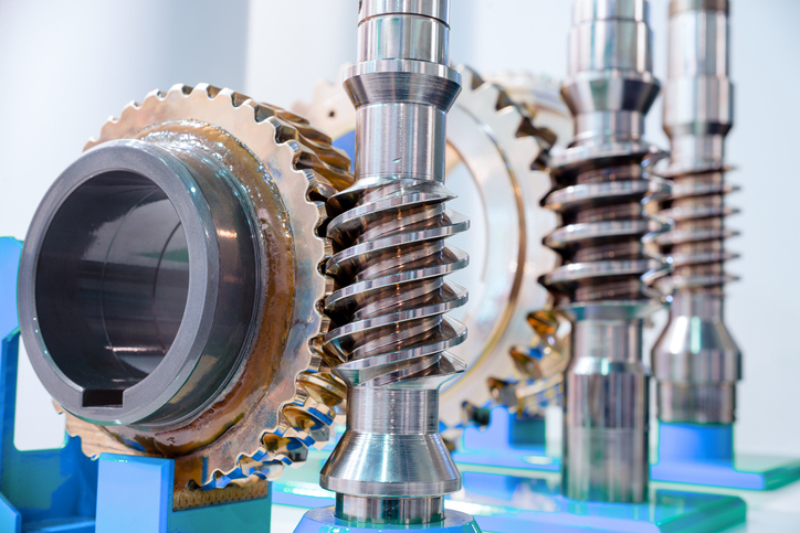
What are worm gears?
A worm gear consists of two primary parts—a shaft with a spiral thread (the worm) and a toothed wheel (worm wheel). An electric motor or engine applies rotational power through the worm, and the screw face of the worm pushes on the teeth of the wheel. The worm is restrained axially, so it rotates the wormgear at right angles. As the worm rotates through the wormgear tooth, lines of contact roll from the tip to the root of the wormgear tooth. At any given instant, there can be 2-3 teeth in contact in varying positions rolling through the worm threads.
For a single-start (thread) worm, each 360-degree full turn advances the gear by one tooth. Because of this, worm gears provide very high reduction ratios, as the ratio is the number of teeth in the wormgear divided by the number of teeth or threads in the worm. As mentioned in ANSI/AGMA 6022-D19, ratios above 30:1 are typically produced with a single thread, while lower ratios often include multiple threads.
Advantages of Worm Gears
Due to their high reduction ratio, worm gears are advantageous for greatly increasing torque or reducing speed. According to ANSI/AGMA 6022-D19, wormgearing is found in applications “transmitting very small amounts of power up to 1000 HP (746KW) and 10 lb in (1.13 Nm) up to 3 000 000 lb in (339 000 Nm) output torques.” Worm speeds can extend up to 10,000 rpm.
Worm gears provide very quiet operation.
Disadvantages of Worm Gears
As with all great things, worm gears are not without their disadvantages. While the high reduction ratio works extensively in its favor, the sliding movement of the worm gear makes it quite difficult to lubricate and reduces efficiency.
The ANSI/AGMA 6022-D19 Standard
ANSI/AGMA 6022-D19 presents various equations and values pertinent to worm gears, and it offers a general approach to design. As a design manual, this standard covers the design of fine and coarse pitch cylindrical wormgearing operating at right angles and incorporated into machines and mechanisms.
ANSI/AGMA 6022-D19 pertains to the selection of the geometric parameters that constitute good design of cylindrical wormgearing. As such, it features general design considerations (characteristics of wormgearing, loading, ratios, conjugate action, thread profile of a worm, and accuracy requirements), design procedures (number of teeth in the wormgear and the worm axial pitch), contact patterns, modified tooth proportions, run-in procedures, manufacturing practices, and symbols (when applicable, conform to ANSI/AGMA 1012-G05: Gear Nomenclature, Definition of Terms with Symbols).
The power rating for wormgearing is not included in this design manual but is instead part of ANSI/AGMA 6034-C21: Practice For Enclosed Cylindrical Wormgear Speed Reducers And Gearmotors.
ANSI/AGMA 6022-D19: Design Manual For Cylindrical Wormgearing is available on the ANSI Webstore.